Digital Inputs vs Outputs
Every fault starts with one question: what information is the PLC receiving? Learn how inputs and outputs actually work, and how to troubleshoot with evidence instead of guesswork.
Watch Full Lesson
Student Guide
Companion to EP002 — learning objectives, glossary, knowledge-check preview, and field tips, all on one page. The full illustrated PDF will be added as a download later.
View Student Guide →Knowledge Check
Five quick questions to check what stuck. Reveal answers as you go — no score tracking, no pressure.
Start Knowledge Check (OCG-Q002) →The Two Pathways
Imagine a conveyor suddenly stops. The first question isn’t “Is the PLC bad?” The first question is: what information is the PLC receiving?
Every PLC communicates through two basic pathways: inputs and outputs. Understanding these two pathways is one of the most important skills every maintenance technician must master.
What is a Digital Input?
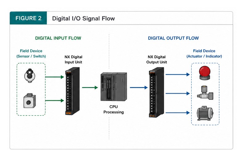
A digital input sends information to the PLC. Think of inputs as the PLC’s eyes and ears.
- Pushbutton
- Limit switch
- Photoeye
- Proximity sensor
- Pressure switch
- Float switch
- Emergency stop
A digital input has only two states: OFF or ON. No in-between.
What is a Digital Output?
Outputs allow the PLC to control equipment. Think of outputs as the PLC’s hands.
- Contactor
- Relay
- Solenoid valve
- Stack light
- Alarm buzzer
- Indicator lamp
When program logic is satisfied, the PLC energizes an output.
How Information Flows
- Photoeye detects box
- Input turns ON
- PLC scans input
- Logic becomes TRUE
- Output energizes
- Motor starts
This is the same pattern behind every automated action in a facility, just with different devices at each end.
Reading the LEDs
An input LED means the PLC is receiving a signal. An output LED means the PLC is commanding an output.
Critical point: an ON output LED does not guarantee the motor is running — there could be a blown fuse, broken wire, failed contactor, tripped overload, or no control power.
Troubleshooting example — machine won’t start:
- Is the RUN light on?
- Is the Input LED ON?
- Is the Output LED ON?
- Does voltage leave the output?
- Is the contactor energizing?
Answering these in order means troubleshooting with evidence instead of guessing.
Common Mistakes
- Confusing inputs with outputs
- Assuming an ON output LED means the load has power
- Replacing sensors without testing them first
- Ignoring PLC indicators
- Forgetting to verify control voltage
Field Tip
“Before you replace any component, ask yourself: what evidence do I have that this device is actually the problem? Following the signal from the input, through the PLC logic, to the output often reveals the real cause of the fault. Inputs receive information. Outputs send commands. Every troubleshooting step starts by figuring out which side of that line the problem is actually on.”